Gas Load — Where Does the Gas Come From?
Estimated time: 25–30 minutes
Identify and describe the five major sources of gas load; explain how each source behaves differently during pumpdown. Competency: M02-COMP-01, Indicators M02-IND-01.01, M02-IND-01.04
Orient
In Module 1, you learned that gas load is the total amount of gas entering the system per unit time — like a steady drip of water into a bathtub that the pump is trying to drain. You also learned that at equilibrium, gas load equals the pump's effective speed — which determines your base pressure.
But "total gas load" is a sum. The critical skill is breaking that sum into its individual contributors, because each source behaves differently and requires a different response.
Think of it like a boat taking on water. "The boat is sinking" tells you the symptom. "There's a hole in the hull, the bilge pump seal is leaking, and it's raining" tells you where to look. Vacuum systems work the same way.
Core Content: The Five Sources of Gas Load
Every vacuum system contends with gas from five distinct sources. Understanding these is the foundation of all vacuum troubleshooting.
Source 1: Bulk Gas (Atmospheric)
What it is: The air that's in the chamber when you start pumping.
How it behaves: This is the easy part. When you begin roughing on R1-A (R1-V-ISO open, R1-V-VENT closed, pump on), the first thing the pump removes is the bulk atmospheric gas — nitrogen, oxygen, water vapour, argon, CO₂ — that was in the chamber at ~950 mbar.
Pumpdown signature: Fast initial pressure drop. On R1-A, you'll see R1-G-CH fall rapidly from ~950 mbar to roughly 1–10 mbar within minutes. This is bulk gas removal — viscous flow, the pump at its most efficient.
Key insight: Bulk gas removal is fast because the gas is dense and flows like a fluid (viscous flow regime). This is not the stage that causes problems. The problems start when the bulk gas is gone and the pump starts fighting the other four sources.
Source 2: Surface-Adsorbed Water
What it is: Water molecules that stick to every internal surface of the chamber, walls, O-rings, fixtures, and sample holders.
How it behaves: Water is the dominant gas load in most rough vacuum systems. Even in a "clean" chamber, several monolayers of water molecules are adsorbed on every surface — adsorption is gas molecules sticking to a surface, like dust clinging to a sticky surface.
When you pump down, these water molecules slowly desorb (release from the surface back into the gas phase) — desorption is the reverse, like that dust falling off when conditions change. Together, adsorption and desorption are the constant tug-of-war between surfaces holding gas and vacuum pulling it away.
Pumpdown signature: This is why pumpdown appears to "stall" below about 1 mbar. The bulk gas is gone, but water keeps coming off the walls. The pump is now fighting surface desorption rather than bulk gas removal.
Key insight: Surface water is the reason that a chamber pumped down for the first time in a week takes longer to reach low pressure than one that was pumped down yesterday. The overnight exposure allows more water to accumulate on surfaces.
Why it matters for troubleshooting: A technician who doesn't understand surface water will see the pumpdown stall at 0.1 mbar and think something is wrong. A technician who does understand it will recognise this as normal and check whether the desorption rate is decreasing over time — which is the expected pattern.
Source 3: Outgassing (Material Desorption)
What it is: Gas molecules trapped deeper within chamber materials — in the bulk of metals, polymers, elastomers (like O-ring seals), and any objects inside the chamber. Outgassing is gas escaping from materials under vacuum — think of a wet sponge slowly releasing water as pressure drops around it.
How it behaves: Outgassing is slower than surface desorption. Gas molecules must diffuse from within the material to the surface before they can be pumped away. This is a diffusion-limited process — it decreases over time, but slowly.
Pumpdown signature: A gradually decreasing gas load that persists for hours or even days. On a first pumpdown after the chamber has been open for a long time, outgassing can dominate the gas load below about 10-1 mbar.
The bake-out concept (awareness only): In high-vacuum and ultra-high-vacuum systems, operators heat the chamber walls to 150–250°C to accelerate outgassing. This drives trapped gas out faster, so the system reaches lower pressures sooner. On the R1-A training rig, bake-out is not used — but understanding why it exists helps you appreciate the scale of the outgassing problem in more demanding applications.
Key insight: Outgassing rate decreases over time. If you plot gas load versus time, outgassing produces a curve that slopes downward.
A leak, by contrast, produces a flat line. This distinction is critical for diagnostics — and you'll practise it in the rate-of-rise analysis later in this module.
You can now name three of the five gas load sources (bulk gas, surface water, outgassing) and describe how each behaves during pumpdown. The remaining two sources — permeation and leaks — complete the picture and introduce the key diagnostic distinction between constant and decreasing gas loads.
Source 4: Permeation
What it is: Gas molecules that diffuse through the walls of the chamber itself, or through seals (particularly elastomer O-rings). Permeation is gas slowly diffusing through a solid material without any visible hole or crack — like moisture gradually seeping through a leather glove.
How it behaves: Permeation is driven by the pressure difference between atmosphere outside (~950 mbar) and vacuum inside. Gas molecules — especially helium, which is very small — can slowly pass through solid materials.
Pumpdown signature: Permeation produces a small, constant gas load. It doesn't change over time (unlike outgassing, which decreases).
In rough vacuum systems like R1-A, permeation is usually negligible compared to surface water and outgassing. It becomes important in high-vacuum and ultra-high-vacuum systems where the other gas sources have been minimised.
Key insight: You're unlikely to encounter permeation as a significant problem in rough vacuum systems. But understanding that it exists helps you appreciate why ultra-high-vacuum systems use metal seals instead of elastomer O-rings — metal is far less permeable.
Source 5: Leaks
What it is: Unintended connections between the chamber interior and atmosphere (real leaks) or trapped volumes of gas inside the system (virtual leaks).
Real leaks are physical pathways — cracks, damaged O-rings, loose fittings, porous welds — that let atmospheric gas flow directly into the chamber. The gas load from a real leak is constant (it doesn't decrease over time, because atmosphere is an unlimited reservoir).
Virtual leaks are trapped pockets of gas — for example, a bolt hole with a blind thread, or a gap between two poorly fitted surfaces where air gets trapped during assembly. When you pump down, this trapped gas slowly leaks into the chamber.
The gas load from a virtual leak decreases over time (the trapped volume eventually empties), which makes it look like outgassing. Virtual leaks are notoriously difficult to find.
Pumpdown signature:
- Real leak: Constant gas load. Pressure reaches a floor and stays there (or rises at a constant rate in ISOLATED state).
- Virtual leak: Decreasing gas load that mimics outgassing, but with a different time constant. Eventually empties out.
Key insight: The distinction between real leaks, virtual leaks, and outgassing is one of the most important diagnostic skills in vacuum technology. Module 2 gives you the framework; you'll develop the skill through practice in the synchronous session.
Basic Vacuum Practice — Varian
Basic Vacuum Practice, Ch. 3, pp. 66–80: Outgassing mechanisms — surface desorption, bulk diffusion, and permeation processes with molecular-level diagrams.
This extract covers the outgassing mechanisms you've just encountered — surface desorption, bulk diffusion, and permeation. As you read, pay attention to the molecular-level diagrams showing how gas is released from different depths within materials, and how these mechanisms operate on different timescales.

Safety Hazards Associated with Vacuum System Leaks
Leaks are not just a performance problem — they can be a safety problem. While the R1-A training rig operates with atmospheric air and presents minimal chemical hazard, real-world vacuum systems often involve gases and conditions where leaks create genuine risks:
Toxic or hazardous gas exposure. In process vacuum systems (semiconductor fabrication, chemical vapour deposition, materials processing), the chamber may contain toxic, corrosive, or flammable process gases. A leak that allows these gases to escape into the workspace — through a cracked fitting, a failed seal, or a damaged exhaust line — can expose personnel to dangerous concentrations. Even "small" leaks can accumulate hazardous gas levels in poorly ventilated spaces.
Contaminated exhaust. The pump exhaust carries whatever gases the pump removes from the chamber. If the chamber contains hazardous process gases, the exhaust line carries those gases too.
A leak in the exhaust plumbing, a failed exhaust filter, or a degraded exhaust hose can release contaminated gas directly into the work area. This is why exhaust lines in process vacuum systems are typically routed to external ventilation or scrubber systems — and why checking exhaust integrity is part of routine maintenance.
Implosion risk. A vacuum chamber is under external atmospheric pressure — at sea level, roughly 10 tonnes per square metre of surface area. If a chamber wall, viewport, or fitting is weakened (by corrosion, impact damage, or manufacturing defect), the external pressure can cause sudden, catastrophic inward collapse.
Glass viewports are particularly vulnerable. While implosion events are rare in well-maintained systems, the energy released is significant and can project fragments at high speed.
The practical takeaway: When you encounter a leak during diagnostics, your first concern is always what gas is leaking and where is it going? On the R1-A, the answer is simply "air" — no chemical hazard. But the habit of asking that question starts here, because in the field, the answer determines whether a leak is a performance issue you troubleshoot or a safety issue you evacuate from.
Basic Vacuum Practice — Varian
Basic Vacuum Practice, Ch. 3, pp. 82–87: Virtual leak paths — cross-section diagrams showing trapped volumes, blind holes, and O-ring groove geometries that create virtual leaks.
This extract illustrates the virtual leak paths discussed above. Study the cross-section diagrams carefully — trapped volumes and blind holes are common sources of persistent gas loads that mimic real leaks but eventually exhaust themselves.
Gas Load Summary Table
| Source | Time Behaviour | Typical Magnitude (rough vac) | Responds to Bake-out? |
|---|---|---|---|
| Bulk gas | Removed quickly | Dominant above ~1 mbar | N/A |
| Surface water | Decreases over hours | Dominant 1–10-1 mbar | Yes |
| Outgassing | Decreases over hours–days | Significant below 10-1 mbar | Yes |
| Permeation | Constant | Usually negligible in rough vac | No |
| Real leak | Constant | Variable — depends on leak size | No |
| Virtual leak | Decreases (then stops) | Variable — depends on trapped volume | No |
Visualising the Gas Load Breakdown
The chart below shows how the five gas load sources overlap during a typical pumpdown. As you study it, notice how the dominant source shifts from bulk gas at the start to surface water and outgassing at lower pressures — this is why pumpdown behaviour changes so dramatically as pressure falls.
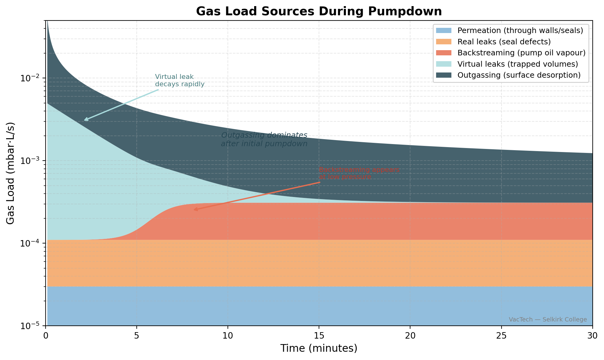
Notice that the constant-rate sources (permeation and real leaks) form flat bands, while the time-dependent sources (surface water and outgassing) slope downward. This visual pattern directly mirrors the rate-of-rise signatures you will analyse in Lesson 3.
Misconception: When pumpdown slows below 1 mbar, the pump is losing performance.
Reality: The pump is working just as hard. What's changed is the gas source. Below ~1 mbar, you've removed the bulk gas and entered the regime where surface water and outgassing dominate.
These sources are diffusion-limited — the gas comes off surfaces slowly, regardless of how fast the pump can remove it. The pump isn't the bottleneck; the gas supply is.
This is the same physics you encountered in Module 1 (the transition from viscous to molecular flow), but now you understand the material science behind it.
What You Can Now Do
By the end of this section, you can:
- Name the five sources of gas load (bulk gas, surface water, outgassing, permeation, leaks)
- Describe how each source behaves differently during pumpdown
- Explain why pumpdown slows below ~1 mbar (it's the gas source, not the pump)
- Distinguish time-dependent sources (surface water, outgassing, virtual leaks) from constant sources (permeation, real leaks)
- Describe the concept of bake-out and explain why it addresses surface-related gas sources
Next Steps
Now that you know where gas comes from, the next lesson focuses on a critical diagnostic tool: the rate-of-rise test. This is how you tell outgassing from leaks — by watching what the pressure does when the pump is disconnected.