Pumping Performance — Speed, Ultimate Pressure & the Oil Mist Filter
Estimated time: 20–25 minutes
Explain pumping speed and ultimate pressure as performance concepts; describe the function of R1-FLT-EXH in detail; describe backstreaming risk. Competency: M06-COMP-02, Indicators M06-IND-02.01, M06-IND-02.03
Orient
You've learned what pumps are and how they work. This lesson focuses on how to describe pump performance and one critical contamination risk: backstreaming through the system and oil mist through the exhaust.
Core Content: Pumping Speed
Pumping speed is the volume of gas a pump can remove per unit time — measured in litres per second, it tells you how fast the pump can clear gas from the system. Units: litres per second (L/s) or cubic metres per hour (m³/h).
What it means: A pump with a speed of 10 L/s can process 10 litres of gas per second at the inlet pressure. If the inlet pressure drops (because gas is being removed), the pump processes less gas per second in absolute terms — but the volume throughput stays approximately constant over its operating range.
What it doesn't mean: Pumping speed is NOT the same as effective speed at the chamber. Module 3 taught you that conductance losses in the connection reduce the speed delivered to the chamber. A 10 L/s pump connected through a narrow foreline might only deliver 3 L/s of effective pumping at the chamber.
Pumping speed curve: Every pump has a characteristic curve showing how pumping speed varies with pressure. Most pumps have a plateau of relatively constant speed across their operating range, then speed drops sharply near their ultimate pressure.
Core Content: Ultimate Pressure
Ultimate pressure (base pressure) is the lowest pressure a pump can achieve on its own — the point where the pump's removal rate equals the total gas entering the system, and pressure stops falling. It is measured when pumping on a sealed, clean, leak-free system.
What determines it: At ultimate pressure, the pump's throughput equals the gas load from the pump itself (internal outgassing, internal leaks, oil vapour). The pump is fighting its own gas emissions.
Why it matters: A pump's ultimate pressure sets the floor for system performance — the system can never go below the pump's ultimate pressure, even if the chamber is perfectly clean. But in practice, the system base pressure is usually determined by chamber gas load (M02) and conductance (M03), not by pump ultimate pressure.
You can now explain the two key performance concepts: pumping speed (volume per unit time) and ultimate pressure (the lowest achievable pressure). Next, you'll examine two critical contamination concerns — what happens to the oil at the exhaust (R1-FLT-EXH) and what happens when oil goes the wrong way (backstreaming).
Core Content: R1-FLT-EXH — The Oil Mist Filter
R1-FLT-EXH is the oil mist filter on R1-A's exhaust line. You've seen it on the schematic since Module 1. Now you'll be able to explain its full role.
What it does: Captures oil aerosol from the rotary vane pump's exhaust before it enters the workspace.
Why it's needed: When R1-P-RP compresses gas, the oil that seals the vanes gets aerosolised — tiny oil droplets are carried with the exhaust gas. Without R1-FLT-EXH, this oil mist would be released into the room. Oil mist is:
- A health hazard (inhalation of fine oil particles)
- A contamination risk (oil settles on surfaces near the exhaust)
- An environmental concern (especially with synthetic or fluorinated pump oils)
How it works: The exhaust gas passes through a filter element (typically a coalescing filter) that captures the fine oil droplets. The coalesced oil drains back to the pump's oil reservoir. Clean gas exits to atmosphere.
Maintenance indicator: If the filter element becomes saturated or blocked, exhaust back-pressure increases — which reduces the pump's effective speed and can cause oil to be pushed out through other paths. A blocked exhaust filter is a maintenance issue that shows up as degraded pump performance.
Basic Vacuum Practice — Varian
Basic Vacuum Practice, Ch. 4, pp. 116–122: Ion pump operating principle — cathode sputtering, gas ionisation, and titanium gettering shown in cell-level and system-level diagrams.
This extract shows the ion pump operating principle — cathode sputtering, gas ionisation, and titanium gettering at both cell-level and system-level views. Understanding this capture mechanism helps explain why ion pumps require no moving parts and produce no contamination.
Core Content: Backstreaming — Oil Going the Wrong Way
Backstreaming (introduced in M02, Lesson 4) is the migration of pump oil vapour backward through the foreline toward the chamber. R1-FLT-EXH handles oil going out the exhaust; backstreaming is oil going in the other direction.
When it's worst: At very low pressure with minimal gas flow. There's no "wind" pushing oil vapour back toward the pump — the vapour can drift freely toward the chamber.
Backstreaming is a perfect illustration of why the Invisibility Principle matters. Oil vapour migrating toward your chamber produces no sound, no smell, no visible trace — until the contamination is already established.
The only evidence arrives through your instruments: elevated base pressure, unexpected hydrocarbon signatures. This is why monitoring protocols exist for conditions that your senses will never detect.
How it's controlled:
- Foreline traps: Cold surfaces or adsorbent materials in the foreline that capture oil vapour before it reaches the chamber (introduced as an R2-A component in M05)
- Gas ballast: A controlled air leak into the pump during compression that increases gas flow and sweeps oil vapour toward the exhaust rather than the inlet
- Isolation: Closing R1-V-ISO when the pump runs at base pressure for extended periods
- Oil-free pumps: Scroll and diaphragm pumps eliminate backstreaming entirely
Connection to diagnostics: If a system shows elevated base pressure with hydrocarbon species (RGA mass spectrum from M02), backstreaming from the roughing pump is a leading hypothesis — especially if the system has been pumping at low pressure for extended periods without a foreline trap.
Basic Vacuum Practice — Varian
Basic Vacuum Practice, Ch. 2–3, pp. 39–90: Pump type comparison — individual cross-sections of rotary vane, diffusion pump, and turbomolecular pump.
This extract provides cross-sections of rotary vane, diffusion pump, and turbomolecular pump designs side by side. Compare the internal geometries to see how each pump type achieves gas compression through fundamentally different mechanisms.
Visual: Pump Performance Curve
A pump's performance is best understood from its characteristic curve. The following chart shows how pumping speed varies across the pressure range for a typical rotary vane pump, and illustrates the difference between the speed at the pump inlet and the effective speed delivered to the chamber.
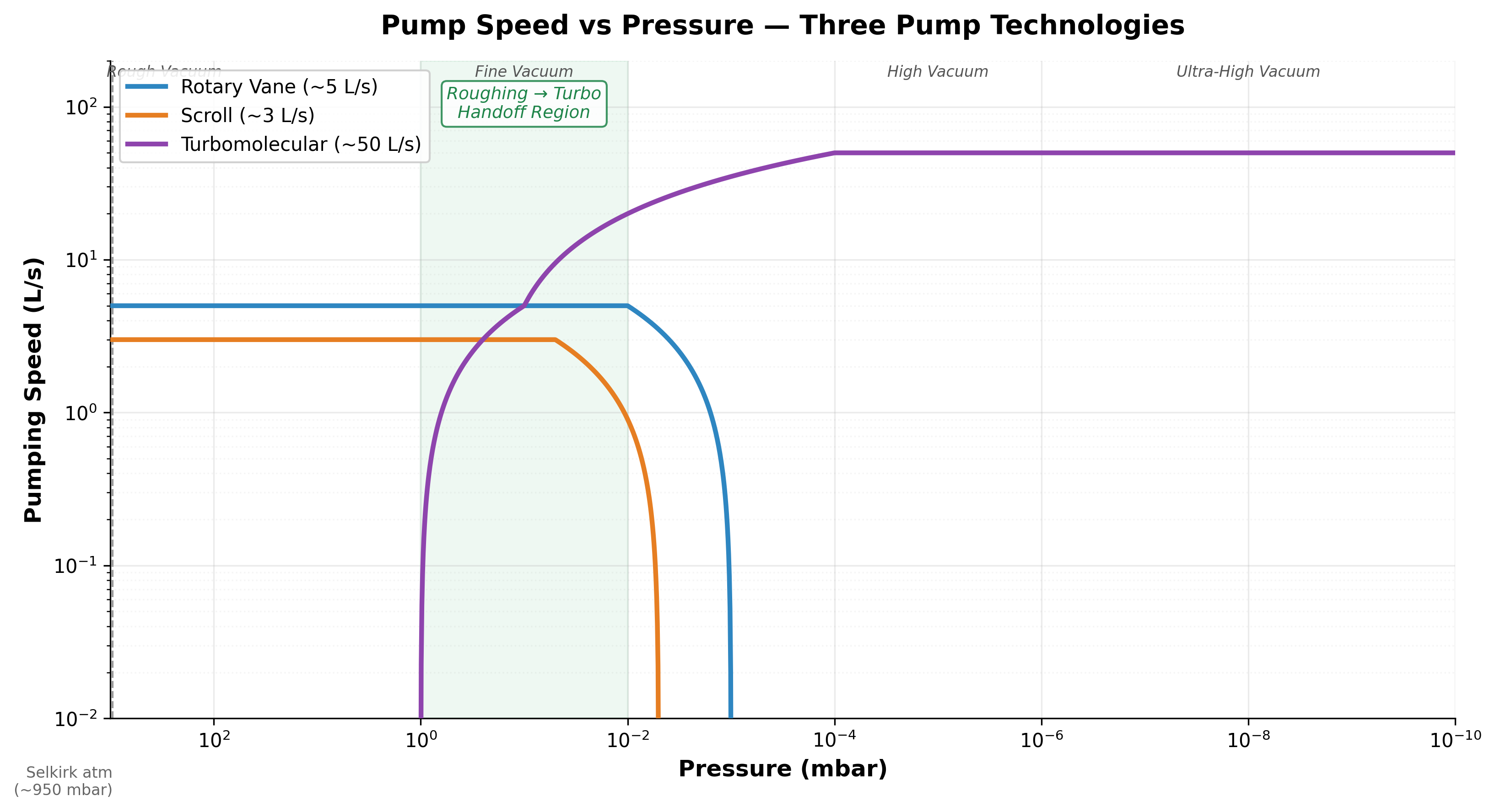
Note the gap between the two curves — this is the conductance penalty from Module 3. A pump may be rated at 10 L/s, but if the foreline connecting it to the chamber has limited conductance, the chamber may only experience 3–5 L/s of effective pumping. When analysing why a system pumps slowly, the performance curve reminds you to consider both pump capacity and the plumbing between pump and chamber.
Visual: R1-FLT-EXH Oil Mist Filter — Detail Diagram
The text above describes what R1-FLT-EXH does and why it matters. The following diagram shows the filter's internal structure so you can see how exhaust gas flows through the coalescing element, how oil droplets are captured and returned to the pump, and where a blockage would cause back-pressure.
Basic Vacuum Practice — Varian
Basic Vacuum Practice, Ch. 8, pp. 231–240: Roots pump operating principle — counter-rotating lobe rotor profiles and compression stages.
This extract shows the Roots pump operating principle — counter-rotating lobe rotor profiles and compression stages. Study how the two lobes intermesh without contact to trap and move gas volumes, and note why this design requires a backing pump to handle the compressed exhaust.
When you look at this diagram, trace the oil's journey: it enters as fine aerosol in the exhaust stream, coalesces on the filter element into larger drops, and drains back to the pump. This recirculation means the pump does not continuously lose oil during normal operation. The important diagnostic detail is the consequence of a blocked element — rising back-pressure is one of the observable symptoms covered in Lesson 5's pump health checklist.
What You Can Now Do
By the end of this section, you can:
- Explain pumping speed and ultimate pressure as performance concepts
- Distinguish between pump speed and effective speed at the chamber
- Describe R1-FLT-EXH's function in detail (capturing exhaust oil mist)
- Explain backstreaming and when it's most likely to occur
- Identify methods for controlling backstreaming (traps, gas ballast, isolation, oil-free pumps)